Motherboard size and case fit before checkout
Check motherboard format, mounting, expansion-card overlap and connector access before choosing a desktop case.
Updated:
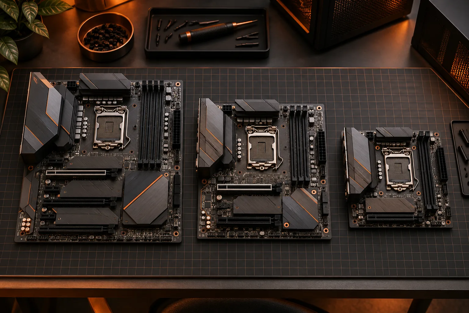
Use the supported-format list, then check the actual layout
A motherboard fits a case when the chassis supports its format and the specific installation leaves the required mounting points, connectors and other components usable. The format name is a first filter rather than a complete fit certificate. Start with the case’s explicit supported-motherboard list, then compare the board drawing with the case installation diagram. If an OEM system uses a different layout, do not assume a retail format label applies.
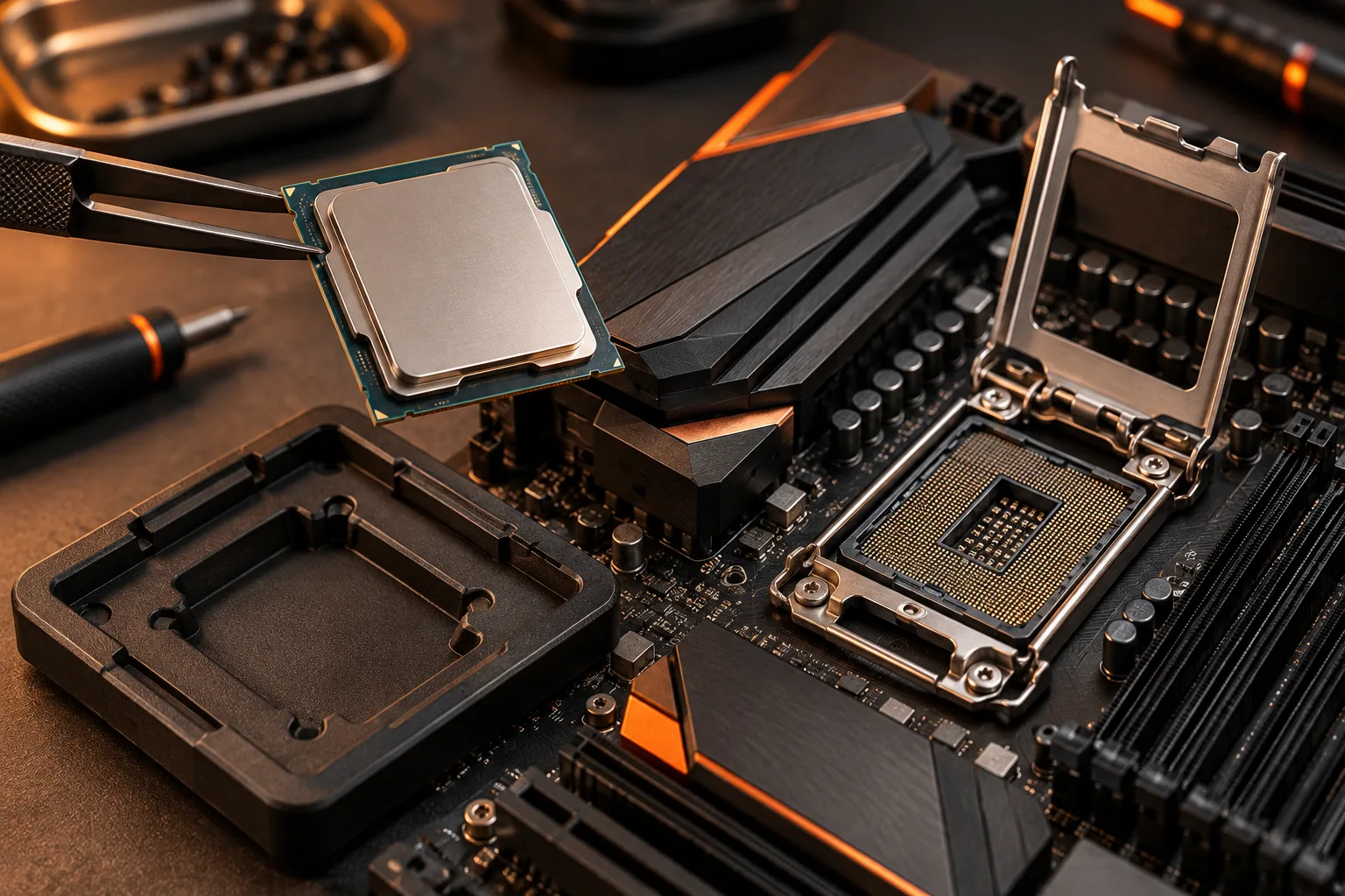
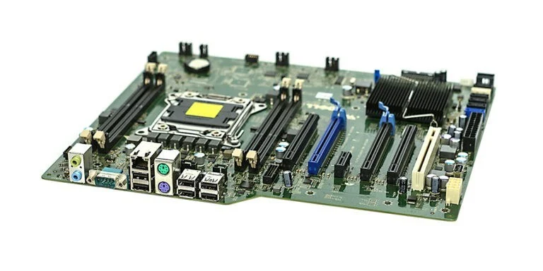
Intel gives familiar reference dimensions: ATX is 12 by 9.6 inches, while micro-ATX is 9.6 by 9.6 inches. Exact product dimensions and the case maker’s support statement still matter. The archival motherboard photograph is useful because it shows that a board is more than its outline: sockets, expansion slots and cable connectors occupy particular positions.
Intel: motherboard formats and component layout ?
A smaller board does not prove the whole computer is smaller
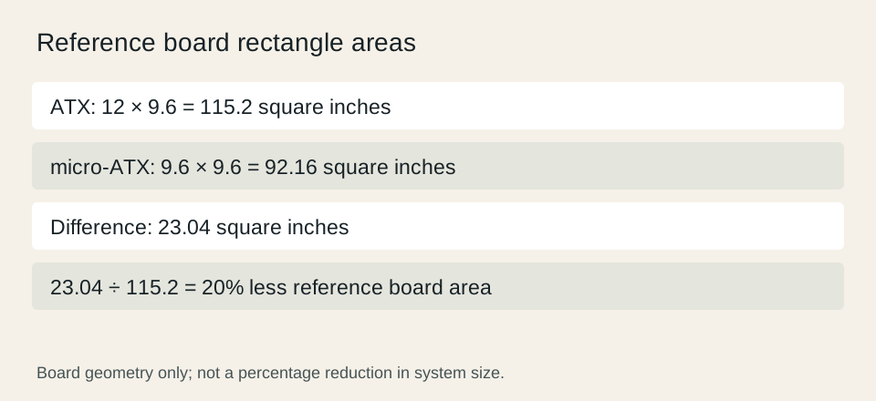
Using those rectangular reference dimensions, ATX occupies 115.2 square inches and micro-ATX occupies 92.16 square inches. The difference is 23.04 square inches, or 20% of the ATX rectangle. This geometric comparison describes board area only. It does not say that a micro-ATX computer is 20% smaller, quieter or cheaper; the case, cooling system and attached components determine other constraints.
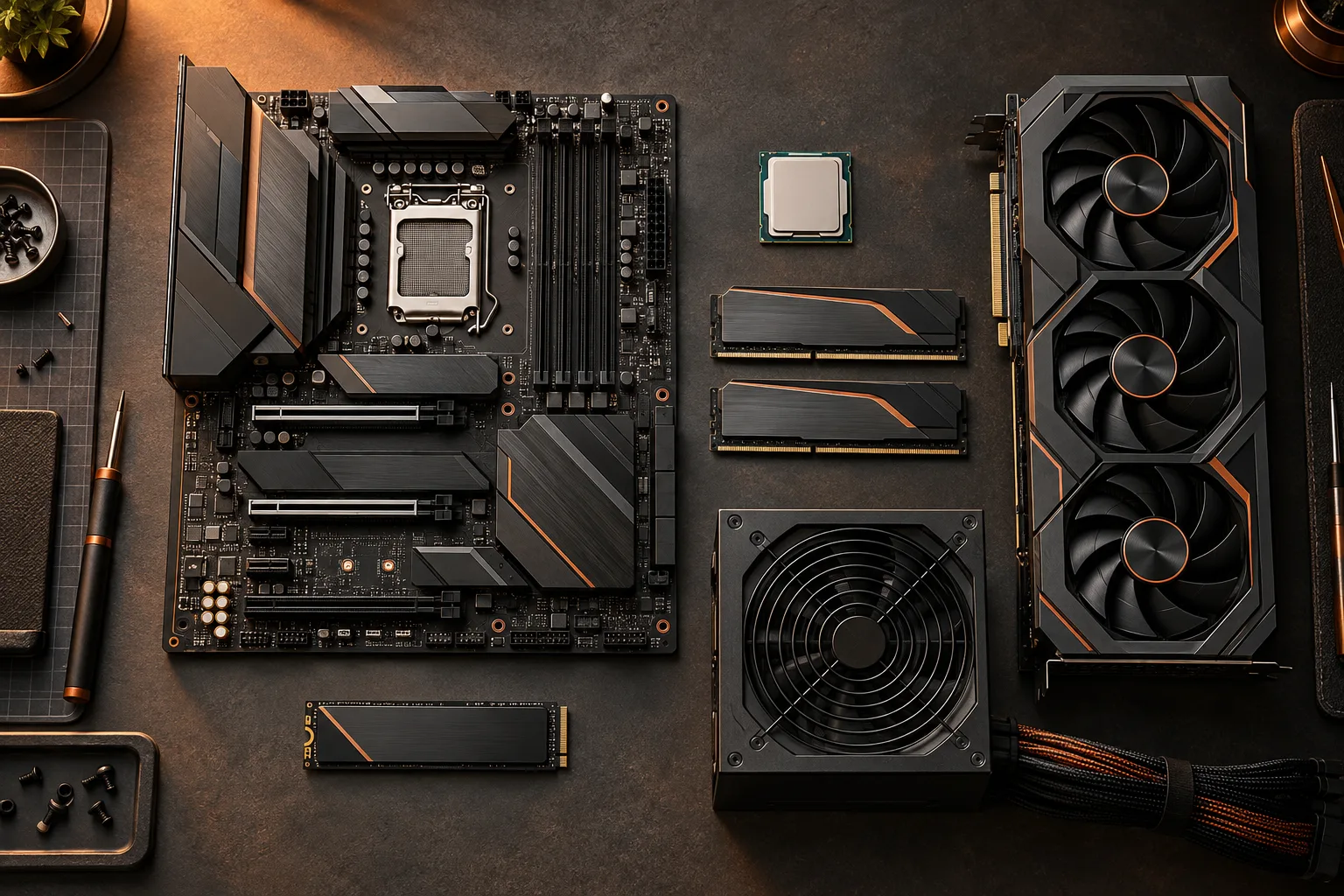
Create separate rows for board support, cooler height, graphics dimensions and power-supply format. A case can accept a smaller motherboard while a particular graphics card remains too long. Conversely, choosing a larger case does not repair a missing supported mounting arrangement. Each row has a different reference document and should remain separate in the purchase record.

Account for memory height and connector access
Memory modules stand above the motherboard surface, and nearby cooling hardware can affect the usable space. The older DDR3 module photo shows the module’s physical outline and label, not a recommendation for a current board. Use the height of your actual kit and the clearance guidance for the chosen cooler. The motherboard form factor does not encode the height of an installed memory module.
Consider access to the power connectors and internal headers as well. A part can sit inside the chassis yet leave an intended connector difficult or impossible to use in the documented arrangement. Compare the installation diagrams before purchase, especially if a radiator, large cooler or unusually long expansion card will occupy the same region. Do not infer clearance from a promotional photograph taken without the relevant parts installed.
Read the graphics-card envelope against the final case setup
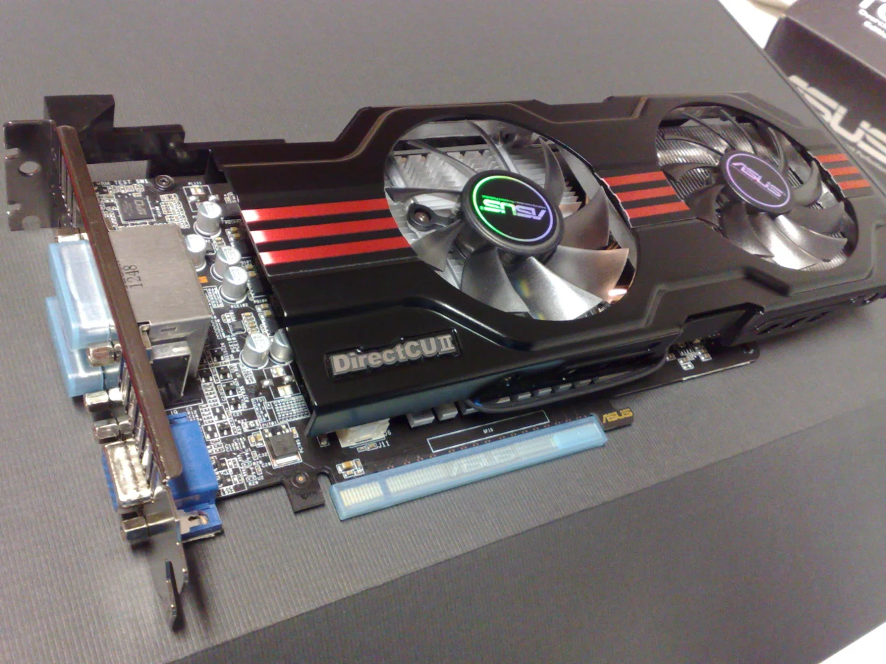
The graphics-card photograph shows a cooler and bracket extending beyond the circuit-board connector. This is why the complete installed envelope matters. Count the occupied expansion positions and compare the card’s length and height with the space remaining after the planned fans or radiator are installed. An empty-case maximum may describe a different arrangement from the one you intend to build.
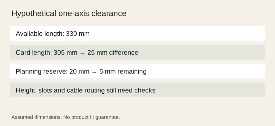
For a hypothetical one-axis check, 330 mm of available length minus a 305 mm card leaves 25 mm. Reserving a further 20 mm in your worksheet leaves 5 mm. The reserve is a planning assumption, not a manufacturer requirement. This arithmetic cannot establish connector routing, mounting alignment or another dimension; it simply makes the length assumption explicit.
Keep the mounting decision grounded in the manuals
Use the documented standoff and mounting arrangement for the exact board and chassis. This buying guide does not replace installation instructions or prescribe a universal screw layout. Keep the case accessory list with the planned build so that required mounting hardware does not become an unexpected purchase. A missing part should be resolved through the documented supply or support route rather than improvised.
Before checkout, retain a compact fit record: supported board format, actual dimensions, selected cooling configuration, complete graphics envelope and PSU arrangement. Mark any unverified item as unresolved. If changing the case resolves one conflict, repeat the other rows against the replacement case. The useful result is a complete physical plan that you can explain, not a single size label treated as proof that every component fits.
Intel: motherboard formats and component layout ?