Measure graphics-card clearance in three dimensions
Compare exact card dimensions with the configured case, including radiator space, occupied slots and cable access. Includes a real MSI dimension example.
Updated:
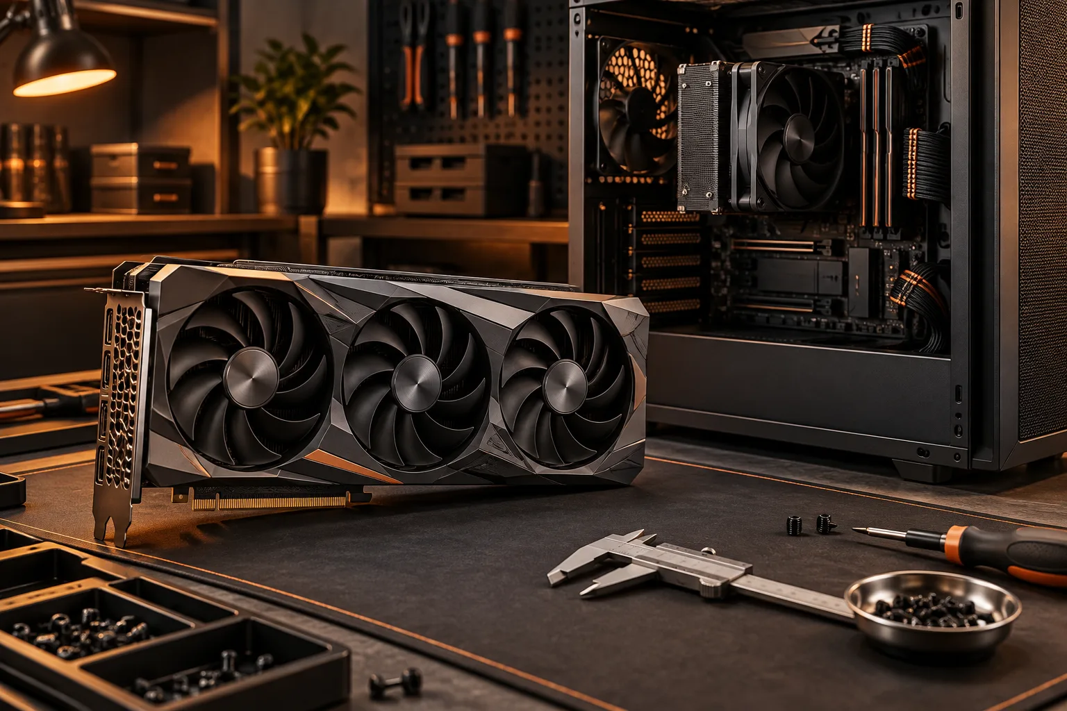
Measure the whole card in the case you will actually build
Graphics-card clearance needs length, height and thickness, plus the installation and cable space required by the exact product. Start with the complete card model, not just the GPU name. Different boards using the same GPU can have different coolers and dimensions. Compare the manufacturer drawing with the case layout after the planned fans, radiator, drives and support hardware are included.
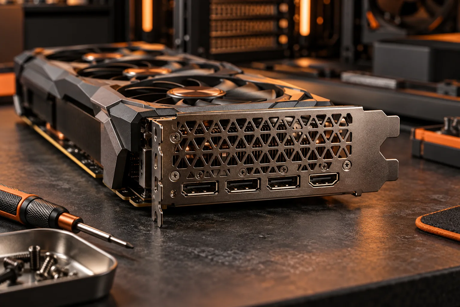
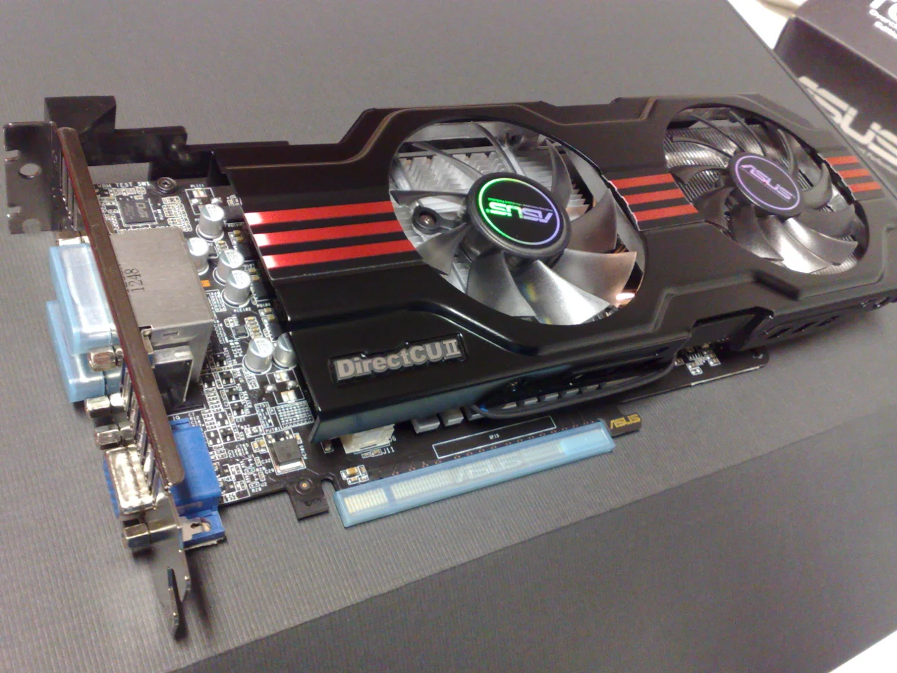
For a real reference, MSI lists the GeForce RTX 5060 8G VENTUS 2X, model G5060-8V2, at 197 × 120 × 41 mm. Those dimensions belong to that particular card. The archival GTX 650 Ti photograph used here shows a cooler and bracket extending around a circuit board, but it is not a photograph or dimensional substitute for the MSI model.
MSI GeForce RTX 5060 8G VENTUS 2X specifications ?
Subtract obstructions from the same reference point
A case maximum can depend on where a radiator or drive cage is installed. Use the configuration that matches your plan, and measure between the reference points shown in the case documentation. Do not subtract a fan thickness twice if the published maximum already assumes that fan. If the reference is unclear, keep the result unresolved rather than producing an impressively precise but meaningless remainder.
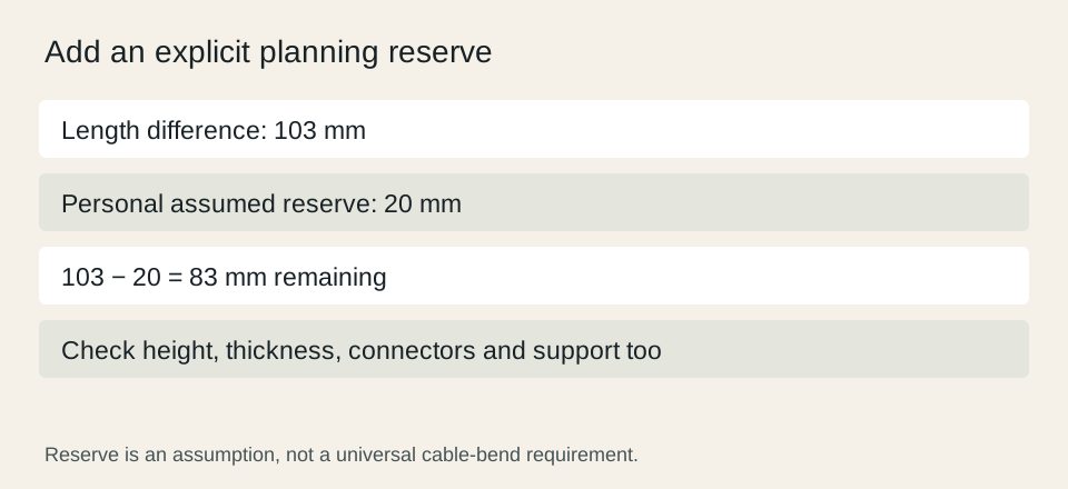
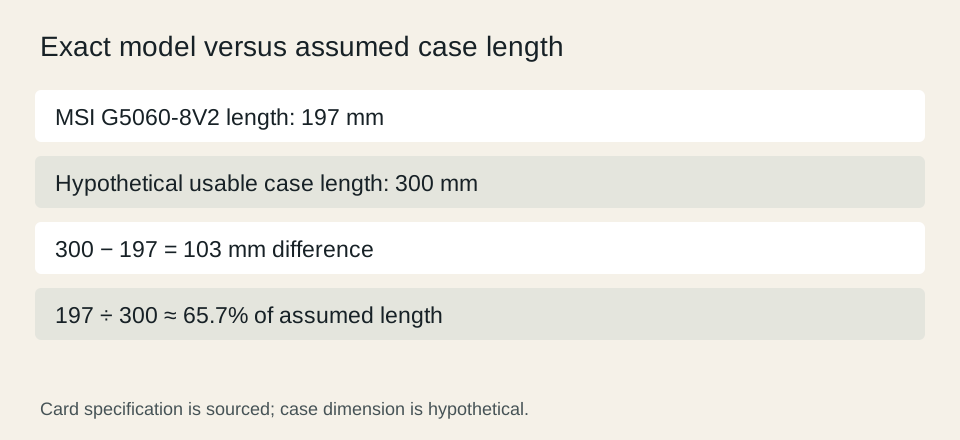
In a hypothetical case with 300 mm of usable length, the 197 mm MSI specification leaves 103 mm before any separately required reserve. A personal 20 mm planning reserve would leave 83 mm. The card occupies about 65.7% of that assumed length, but the percentage is not a fit certificate. The 300 mm case value and reserve are assumptions; only the card dimension is the cited specification.

Inspect neighboring components, not only the case wall
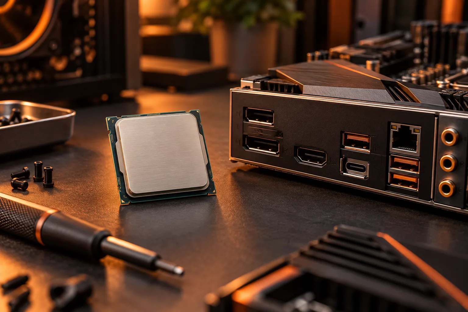
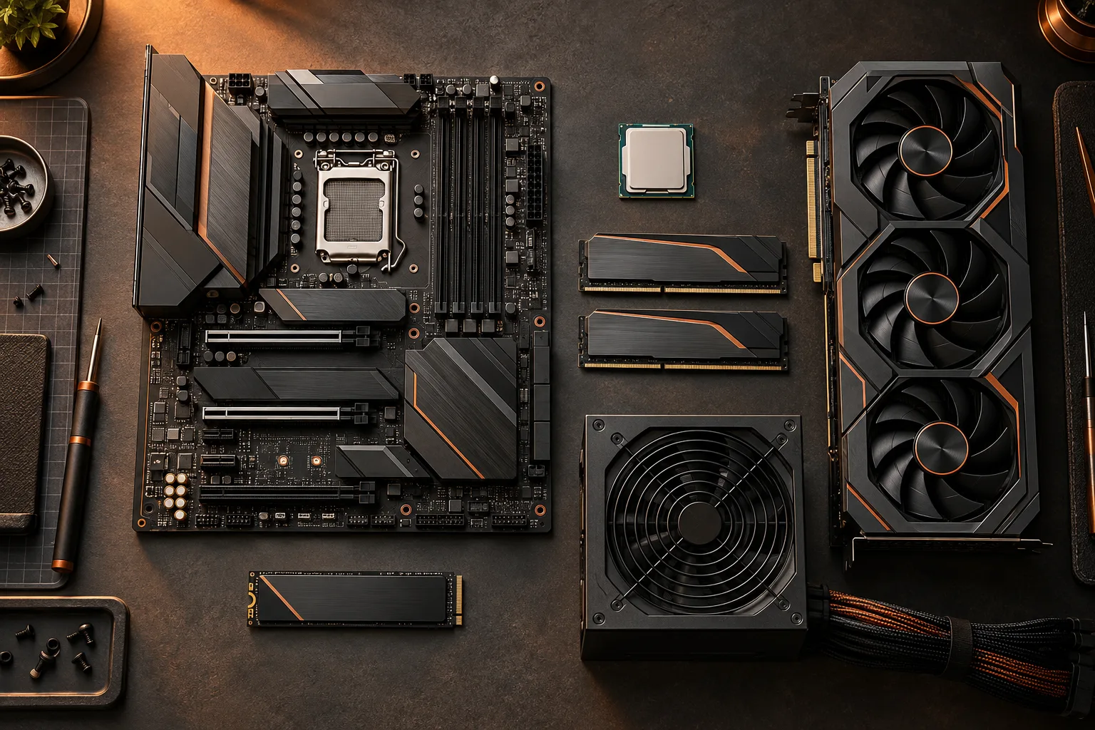
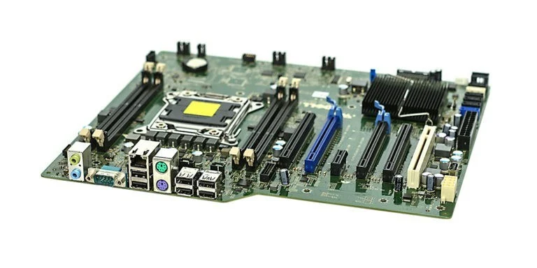
The motherboard photograph shows that expansion slots and nearby connectors have fixed positions. A card can obscure another slot or interfere with access even when the length fits. Make a list of every expansion device you intend to keep and compare the installed card envelope with that layout. An empty adjacent slot in a photograph does not prove that your desired second card will remain usable.
Memory and cooler locations deserve a separate check in compact layouts. The older memory module photo illustrates the installed part’s physical height and label, not a recommendation for this graphics-card example. Include the actual kit and cooler dimensions when the intended arrangement places them near the card or its support hardware. Avoid substituting an unrelated system’s tidy marketing image for your own layout.
Leave cable and support requirements to the exact instructions
Check where the power connector sits and how the manufacturer requires the cable to be routed. Do not impose a universal bend allowance from a different connector design. The specification page establishes the connector requirement, while the installation instructions establish how it should be used. Case height clearance measured to the card alone may omit the space occupied by a connected cable.
Likewise, account for any required bracket or support arrangement. The clearance calculator can subtract a reserve that you supply, but it cannot choose a safe cable route or validate a bracket. A zero remainder means the entered dimensions have no arithmetic margin; it does not guarantee that the card can be inserted, secured and connected in the intended configuration.
MSI GeForce RTX 5060 8G VENTUS 2X specifications ?
Record each dimension as a separate decision
Create rows for length, height, occupied expansion positions, cable route and support hardware. Mark each confirmed only when the manufacturer documentation and your configured-case measurements agree. A card can pass the length row and fail another row. Do not average the results into a score that conceals a decisive conflict.
If one dimension fails, compare an explicitly smaller card version, a different case configuration or another case. Recheck the other rows after every substitution. The useful result is a documented installation envelope with identifiable sources and assumptions. We have not installed the MSI card in your case, tested its temperatures or measured its performance, so this guide makes none of those claims.
MSI GeForce RTX 5060 8G VENTUS 2X specifications ?