Plan a clear airflow path before adding more fans
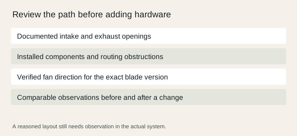
Draw the intended intake and exhaust path, check obstructions and fan direction, then evaluate changes with comparable observations.
Updated:
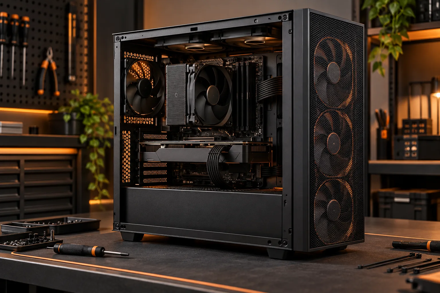
Draw the path through the actual case first
Before buying additional fans, sketch where air can enter the case, pass the installed components and leave. Include the case panels, filters, drive cages and the space around the computer. A list of fan mounting positions is not the same as an unobstructed airflow path. Start with the case documentation and the arrangement you can actually install.
The motherboard photograph illustrates the component area that the plan must serve. It is an archival board, not an airflow measurement or a current case layout. In your drawing, place the real processor cooler, graphics card and major obstructions rather than treating the interior as an empty box. This helps expose an assumption about access or clearance before another purchase.
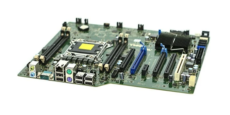
Account for the graphics card as an installed obstruction
The archival graphics-card photograph shows a substantial cooler assembly attached to a card. It helps explain why a long installed component can change the available interior space. It does not establish how another card exhausts air or how its fans behave. Use the exact card documentation and the case layout when describing the intended path around it.
Check the chosen card position, nearby expansion devices and cable routes together. A clearance result for the card body does not automatically describe the space available for airflow. Keep that distinction visible in the plan. If the case has several possible fan or radiator arrangements, evaluate the particular combination you intend to use rather than adding together incompatible mounting options.
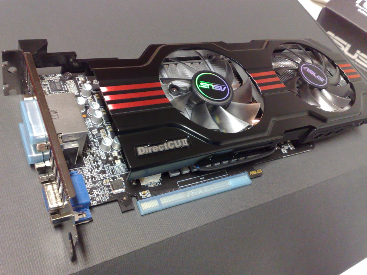
Verify direction from the exact fan documentation
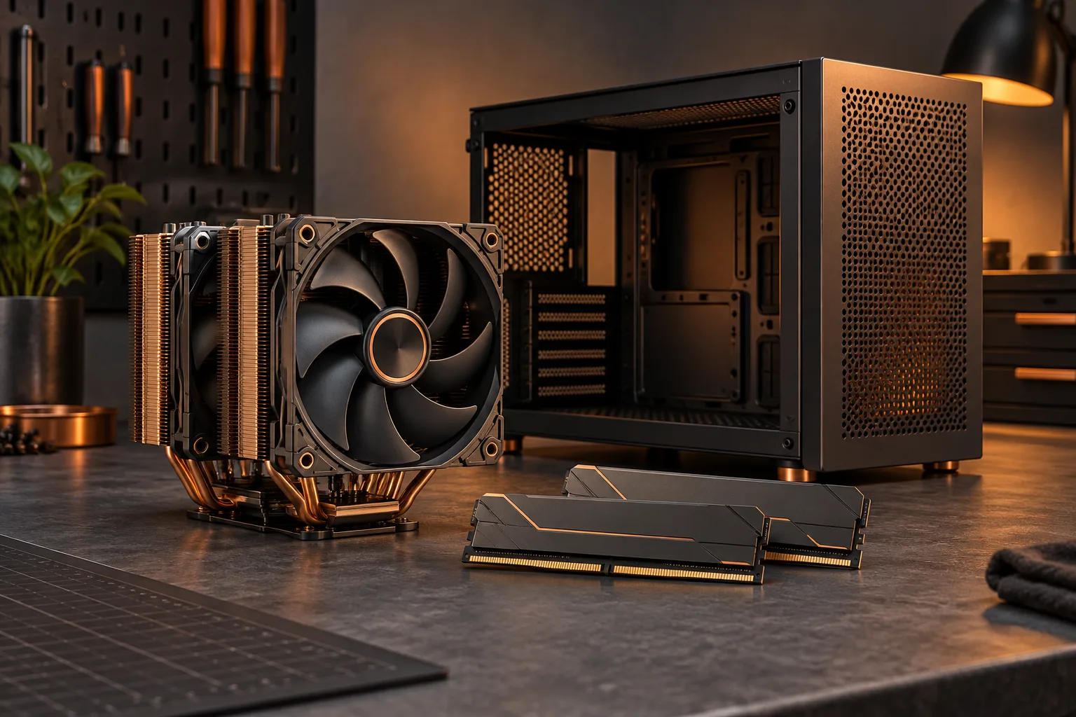
The tower-cooler photograph shows fins and heatpipes that form another part of the interior layout. The direction through that assembly needs to make sense with the case plan, but this archival image is not an installation instruction for your cooler. Consult the cooler and fan documentation before deciding which orientation serves the intended path.
Thermaltake notes that case conditions matter and that reversible SWAFAN blades are an exception to simple appearance-based orientation rules. Follow a documented direction indicator or the exact fan instructions. Do not assume that a logo-facing side always identifies intake or exhaust across all products, especially when different blade versions are available.
Thermaltake: an introduction to chassis airflow ?
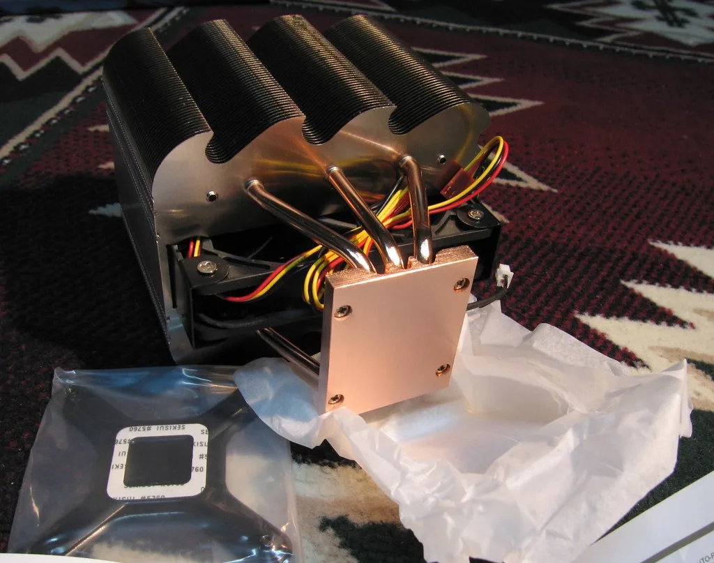
Separate fan count from measured system behavior
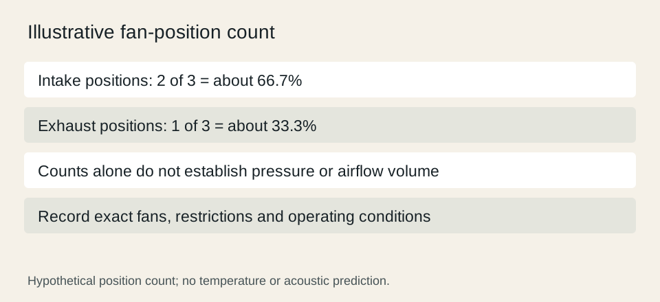
Suppose an illustrative plan contains two intake fans and one exhaust fan. Intake fans account for two of the three positions, or about 66.7%, while exhaust accounts for about 33.3%. Those fractions describe the plan only. They do not establish pressure, airflow volume, temperature or noise because the fans, restrictions and operating conditions have not been measured.
Treat adding a fan as a proposed change with a reason, such as serving a documented mounting position along the intended path. Avoid assigning an invented temperature benefit to it. If you compare configurations, keep the workload, room conditions, software settings and observation method as consistent as practical, and record the differences rather than attributing every change to the new fan.
Use an explicit review before spending more
Review the plan for blocked external vents, unsupported mounting arrangements and unresolved fan direction. Follow the system documentation when cleaning accessible filters or changing components. This guide is a layout and purchasing worksheet, not a guarantee that a particular number of fans will solve a thermal problem. A measured symptom may require a different diagnosis.
Finish with a drawing of the real arrangement, the fan models and directions, the restrictions you identified and the observation that would justify another change. If the current configuration already meets your documented needs, the worksheet does not require an additional purchase. Revisit the plan when a larger card, a different cooler or a new case arrangement changes the space available.